

During the operation of a soybean cleaning production line, frequently encountered issues typically center on incomplete impurity separation, screen clogging or damage, soybean kernel breakage or loss, equipment misalignment or excessive vibration, poor dust removal efficiency, and fluctuations in raw material moisture content or impurity levels. The core strategy for resolving these issues involves a combination of process optimization, equipment calibration, a closed-loop maintenance system, and raw material pretreatment, with the ultimate goal of ensuring an impurity rate of less than 0.5% and a breakage rate of less than 1%.
I. Incomplete Impurity Separation (Impurity Levels Exceed Limits)
1. Symptoms
The finished soybean product contains clods of earth, stones, straw, broken kernels, and moldy grains; conversely, good-quality soybeans are mixed in with the coarse impurities, resulting in high material loss.
2. Causes
Improper Screen Aperture Size: Apertures that are too large allow fine impurities to pass through into the finished product; apertures that are too small cause soybeans to become lodged or result in good beans being discharged along with the impurities.
Inappropriate Airflow/Vibration Amplitude: Insufficient airflow fails to blow away light impurities; excessive airflow carries away good-quality soybeans. A low vibration amplitude prevents proper material stratification, making it difficult to separate coarse impurities.
Uneven Feeding/Material Short-circuiting: Damaged material distribution plates or an excessively thick material layer can cause localized material streams to “rush” directly across the screen surface without undergoing adequate screening.
Insufficient Specific Gravity/Magnetic Separation: Heavy impurities—such as stones and metal fragments—are not removed in advance; this causes wear and tear on the equipment and makes them difficult to separate during the screening process.
3. Solutions
Screen Selection: For primary cleaning, use screens with 8–10 mm round perforations to remove coarse impurities; for fine cleaning, use screens with 3–4 mm oblong perforations to remove broken kernels. Ensure the screen aperture tolerance is within ±0.2 mm.
Airflow and Vibration Parameter Optimization: Control the fan airflow velocity between 1.2–1.8 m/s to ensure all light impurities are carried away while good-quality soybeans remain grounded. Set the vibration frequency between 900–1100 rpm and the amplitude between 3–5 mm to ensure proper material stratification and forward movement.
Uniform Feeding: Repair or replace damaged material distribution plates and install a material spreader at the feed inlet to maintain a uniform material layer thickness of 20–30 mm. Avoid single-sided feeding or localized material piling.
Upstream Impurity Removal: Install a magnetic separator and a specific gravity destoner at the front end of the production line to remove metal fragments and stones in advance, thereby protecting the screens and downstream equipment from damage. Color Sorting Supplement: Moldy and discolored grains are difficult to remove using air screens alone; the addition of a color sorter—with an accuracy of ≥99.9%—effectively eliminates off-color and diseased grains.
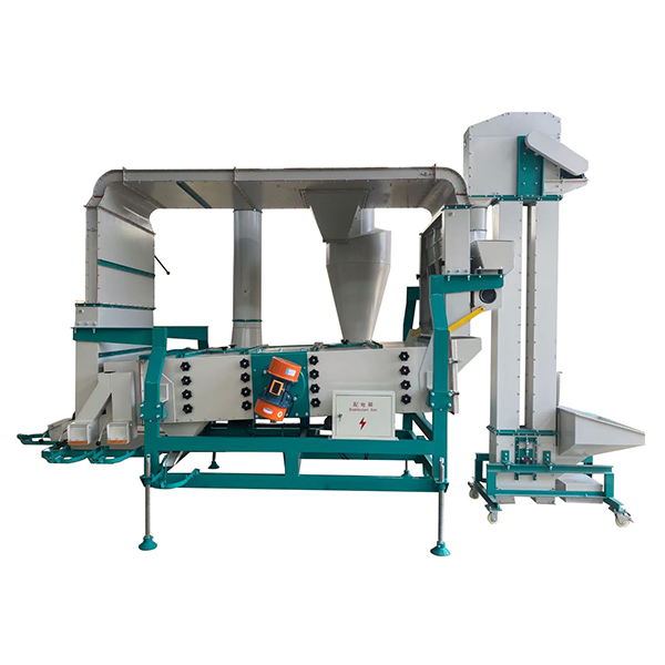
II. Screen Clogging, Bean Jamming, and Damage
1. Symptoms
Material accumulation on the screen surface; slow discharge rate; failure to achieve target throughput; beans becoming jammed in the perforations; screen deformation or perforation; leakage of beans and impurities.
2. Causes
High raw material moisture content: When exceeding 14%, beans become sticky and soil clumps form, adhering to the screen surface and clogging the mesh openings.
High soil content in impurities: Damp soil smears and clogs the screen, particularly during the rainy season or when processing raw materials from southern regions.
Insufficient screen tension: A loose screen vibrates unevenly, making it easy for beans to become jammed in the perforations; tension levels below 50 N/cm increase the risk of deformation.
Worn elastic cleaning balls: The elastic balls used for screen cleaning become aged or fragmented, rendering the cleaning mechanism ineffective and exacerbating hole clogging.
3. Solutions
Moisture Control: Dry or sun-dry raw materials prior to processing to reduce moisture content to 12%–13%; pre-clean high-moisture raw materials to minimize the introduction of soil.
Enhanced Screen Cleaning: Use compressed air (0.4–0.6 MPa) to back-flush the screen during every shift; inspect the elastic cleaning balls weekly and replace them promptly if wear exceeds one-third of their original size.
Standardized Tensioning: Maintain screen tension within the range of 50–60 N/cm, ensuring uniform fastening on all four sides to prevent localized slackness.
Anti-Jamming Design: Select screens featuring oblong or wave-shaped perforations to reduce the likelihood of beans becoming jammed; install anti-jamming baffles along the screen edges.
III. Bean Kernel Skin Damage and High Breakage Rate
1. Symptoms
The finished product contains a high proportion of broken cotyledons and exhibits a poor appearance, negatively impacting both the selling price and subsequent processing stages (such as dehulling and milling).
2. Causes
High Mechanical Impact: The angle of the discharge chute is excessively steep (>60°), or the drop height is significant (>1.5m), causing bean kernels to strike the chute walls or equipment surfaces at high velocity.
Rough Sieve Surfaces/Equipment: The sieve mesh features burrs or protruding weld seams, or the material guide plates have sharp edges, resulting in the scraping and tearing of the bean kernels’ skins.
Excessive Vibration/Airflow: The vibration amplitude exceeds 5mm, or the airflow velocity exceeds 2m/s, causing the bean kernels to bounce violently and collide with one another.
Improper Equipment Clearance: The gaps within machinery—such as destoners or bucket elevators—are set too narrowly, resulting in the crushing of bean kernels as they pass through.
3. Solutions
Reduce Impact: Control the discharge chute angle within the range of 45°–55°; for drop heights exceeding 1m, install buffering sections or rubber liners; at material transfer points, utilize soft guiding mechanisms to prevent hard impacts.
Smooth Equipment Surfaces:Grind and deburr sieve meshes and guide plates, and polish all weld seams; for components that come into direct contact with the beans, utilize 304 stainless steel lined with food-grade rubber.
Adjust Operating Parameters: Adjust the vibration amplitude to 3–4mm and the airflow velocity to 1.2–1.5m/s to prevent excessive bouncing and friction among the bean kernels.
Adjust Clearances: Periodically inspect the clearances within equipment—such as destoners and bucket elevators—and adjust them to the standard values specified in the operating manual to prevent the crushing of beans.
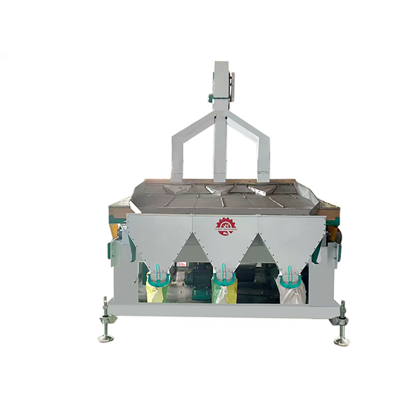
IV. Equipment Misalignment, Abnormal Vibration, and Unusual Noises
1. Phenomena
Material on the screen surface drifts to one side, resulting in uneven distribution (one side thick, the other thin); the machine body vibrates violently and generates excessive noise; the motor overheats, and bolts become loose.
2. Causes
Vibrating motors are out of sync: The angles of the eccentric blocks are asymmetrical (error > 5°), rotational speeds are inconsistent, and the excitation forces are unbalanced.
Vibration damping system failure: Springs have aged or possess uneven stiffness; rubber pads are cracked or deformed.
Uneven installation: The foundation surface flatness error exceeds 2 mm/m; the equipment is rigidly connected to chutes, leading to stress transmission.
Loose/Worn components: Motor mounting bolts or screen mesh fixing bolts are loose; bearings are worn, or the impeller is unbalanced.
3. Solutions
Motor Calibration: Ensure the eccentric blocks of dual-motor systems are symmetrically positioned at 180°, with a phase angle error of ≤ 5°; ensure synchronous belts are tensioned consistently, with a rotational speed difference of ≤ 1%.
Vibration Damping Maintenance: Inspect damping springs regularly; replace them immediately if elasticity has decayed or cracks appear; replace aged rubber pads promptly to ensure uniform load-bearing.
Standardized Installation: Level the foundation to ensure a flatness tolerance of ≤ 2 mm/m; utilize flexible connections for material inlet and outlet ports, maintaining a gap of 10–15 mm to prevent rigid stress transmission.
Fastening and Lubrication: Re-check all bolts monthly (particularly those on the motor and screen frame); replenish lithium-based grease in bearings every 2,000 hours, ensuring the fill volume does not exceed two-thirds (2/3) of the bearing cavity capacity.
V. Poor Dust Removal Efficiency and Dust Spillage
1. Phenomena
High dust levels in the workshop resulting in low visibility; the dust collection fan exhibits insufficient suction power, leading to rapid dust accumulation; the cyclone separator or rotary airlock valve experiences material blockages or dust leakage.
2. Causes
Insufficient Air Volume/Pressure: The fan impeller is worn, drive belts are loose, or rotational speed has decreased; air ducts are clogged or leaking air.
Dust Collection Component Failure: Dust has accumulated on the inner walls of the cyclone separator, causing material blockages; rotary airlock valve blades are worn, leading to air leakage; filter bags are clogged (caked) or damaged. Improper Suction Point Configuration: The placement or quantity of suction inlets is inappropriate, resulting in incomplete dust capture; additionally, if the airflow velocity is too low, dust may settle out or escape.
3. Solutions
Fan Maintenance: Regularly clean dust accumulation from the impeller (replace the impeller if wear exceeds 1/5 of its thickness); tension the drive belts to ensure the fan operates at its rated speed; clean the air ducts and repair any air leaks.
Dust Collection Component Maintenance: Clean dust accumulation from the cyclone separator during every shift; inspect the rotary airlock valve weekly—if blade wear creates a clearance exceeding 2 mm, repair or replace the unit; perform regular dust removal on the filter bags and replace them immediately if they are damaged.
Suction Optimization: Establish 3–4 suction points positioned at the feed end, directly above the screen surface, and at the discharge end of the cleaning screen; maintain an airflow velocity between 1.5 and 2.0 m/s to ensure complete dust capture and prevent any dust from escaping.
Post time: May-25-2026